01 / FIN FORMING
The metal is sliced. The fins are raised.
Sequential cuts create the fin structure integrated with the base.
ARMA / THERMAL MANAGEMENT
Fin and base made from the same metal. Thin fin geometries and heatsink solutions shaped according to your drawings.
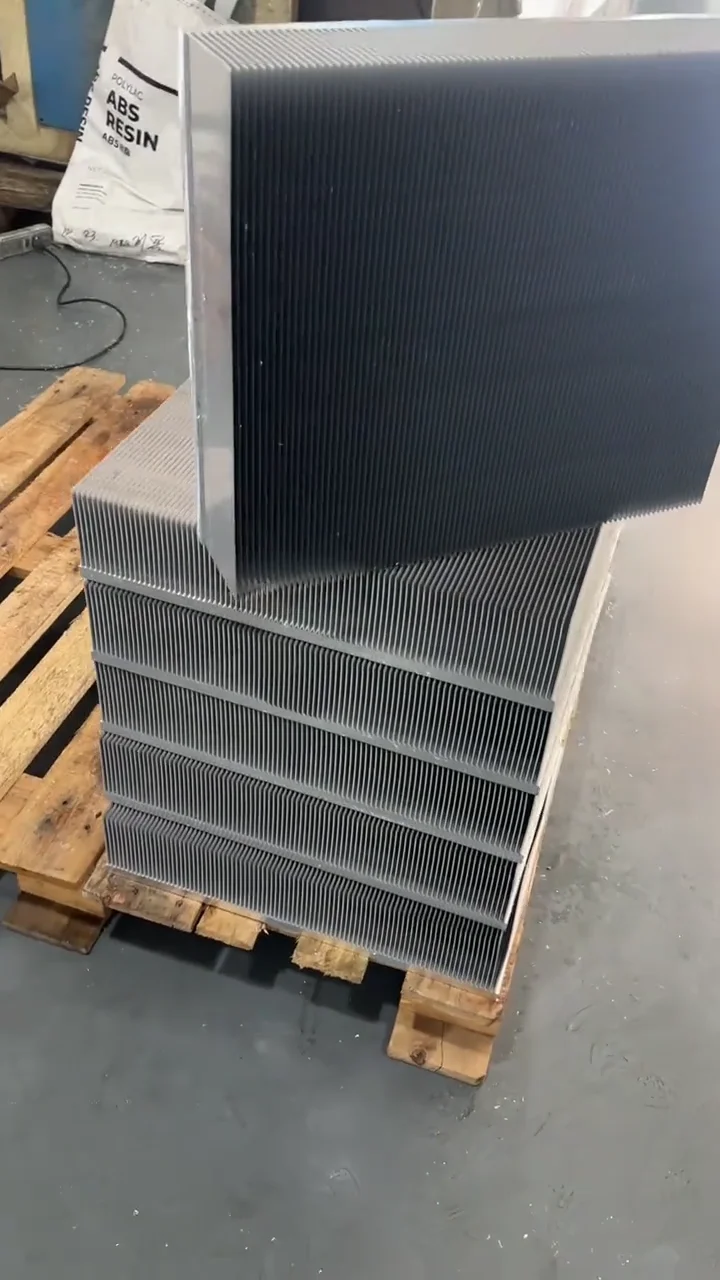
SKIVING TECHNOLOGY
In the skiving process, thin slices are cut and lifted from the surface of the metal to form the fins. This ensures the fins remain part of the same piece as the base.
There is no secondary joint between the fin and the base. Optimal fin spacing, material, and geometry are evaluated in conjunction with airflow, heat load, and available mounting space.
The fin and base are formed from the same metal.
Fin thickness and placement are evaluated based on the project.
Mounting surfaces, connections, and finishing requirements are addressed together.
FROM METAL TO HEATSINK
Short process videos showing the fin forming and finishing stages.
Sequential cuts create the fin structure integrated with the base.
Top milling and brushing complete the finishing process of the part.
These videos are process examples shared by the equipment manufacturer.
TECHNICAL FRAMEWORK
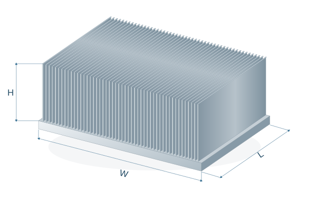
Let's review your design together by defining the length, width, and fin dimensions separately.
SKIVED HEATSINK / REPRESENTATIVE GEOMETRY
FIN CROSS-SECTION / ENLARGED DETAIL
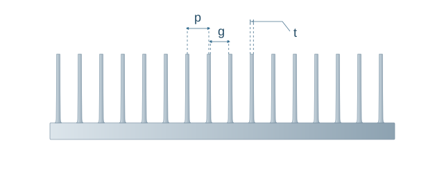
Not to scale. The number and spacing of the fins are illustrated representatively.
These ranges are for preliminary work. The feasibility of the dimensions is verified via technical drawings based on the material, geometry, and tool selection. For the fin pitch, the 1:2–1:10 ratio in the top table of the manufacturer's datasheet is used; this value is not a pitch interval in mm. The definition of the ratio and the net fin clearance are pending confirmation. Base thickness and tolerances are determined on a project-by-project basis.
MATERIAL & DESIGN
We address weight, mounting space, and thermal requirements together. The alloy and material condition are evaluated alongside the manufacturability of the part.
APPLICATION AREAS
Power module, mounting surface, and airflow requirements.
02 / ENERGY & CHARGINGEvaluating heat load and mechanical layout together.
03 / ELECTRONIC SYSTEMSAvailable space, airflow channels, and cooling requirements.
FAQ
In the skiving process, fins are created by cutting and lifting them from a solid block of metal. In extrusion, the profile cross-section is shaped by forcing it through a die. The appropriate method is selected based on material, fin geometry, quantity, and application conditions.
Fin spacing must be evaluated in conjunction with airflow. It is just as important for air to move through the channels as it is to have a large fin surface area. Forced convection and natural convection applications may require different geometries.
Share your technical drawing, material, quantity, mounting area, and critical tolerances. For thermal assessment, include details on heat load, heat source dimensions, ambient temperature, airflow, and target temperature.
FROM DRAWING TO SOLUTION
Share your technical drawing and operating conditions. We will evaluate the material, fin geometry, and finishing options for your project.